Summary
In many steel structures, some bolted connections are designed to stop steel parts from slipping, for example, to avoid misalignment during service. In order to work effectively, these slip-critical or slip-resistant connections rely on defined friction between the faying surfaces. High friction – characterised by a high slip factor – allows for heavier loads. When the faying surfaces are protected against corrosion by a coating system, the slip factor of the coating system needs to be taken into account. This slip factor is not only dependent on the coating itself, but also on surface preparation, maximum dry film thickness and curing conditions.
Zinc silicate coatings are typically specified for faying surfaces, but other paint types – such as zinc epoxies – are also considered, as they are easier to apply. However, zinc epoxy coatings typically have lower slip resistance than zinc silicates, especially at temperatures above the glass transition temperature (TG) of the coating. Despite this, the effect of temperature on the slip resistance of zinc epoxy coatings is rarely discussed in literature.
This technical article explains some of the engineering terms, calculations and other relevant details when determining the slip factor of a zinc silicate coating system, according to Annex G of the European standard EN 1090-2i (Another test procedure can be used – as defined in the Research Council on Structural Connections (RCSC). Specification for Structural Joints Using High-Strength Bolts, August 2014ii – but the literature indicates that the European codes are more conservative in how they measure the strength of a bolted connection).
What is a slip-critical joint?
Slip-resistant bolted connections
A number of methods are used to combine steel sections, including welding, riveting and bolting. Whereas welding and riveting are fixed coupling, bolted connections are used for large structures that are built in sections for easier transport or handling, or when connections need to be dismantled during maintenance and service.
When these connections are exposed to reversed loading or when misalignment over time is unacceptable, then a slip-resistant joint – slip-critical joint – must be usediii.
According to the definition, a slip-critical joint owes its strength to:
- the clamping force pressing together the faying surfaces. This force is obtained by pre-tensioning the bolts, which are typically high-strength
- the preparation of the faying surfaces to obtain a slip factor (EN 1090-2) or slip-coefficient (RCSC Specification) that allows calculation of slip resistance
Measuring slip for coated surfaces
Two standards are referred to when methods for measuring the slip factor are specified:
- Annex G of EN 1090-2: Test to determine slip factor
- Appendix A of RCSC Specification: Testing method to determine the slip coefficient for coatings used in bolted joints
Although the two test standards are similar, it is not possible to make a one-to-one comparison between them. Even if the slip factor has been determined using one test standard, one cannot immediately transfer the result to another standard.
However, E. Maiorana and Carlo Pellegrinoiv present a numerical example to compare various code provisions – from Europe, the United States, Canada, Australia and Japan – to show their performance for a practical case.
They conclude that the European code is the most conservative for the typical cases studied in terms of shear, bearing and combined shear and tension resistance. In the following, we will go through a test with Hempel’s Galvosil according to the European standard, thereby determining a conservative slip factor of a coating system.
The validity of the test results according to other codes or standards must be decided by the specifier. Kulak et al.iii may be a useful reference for comparing results obtained by other standards.
The terminology of the two standardised methods reflects civil engineering terminology more than the terminology of coating engineering.
Purpose of testing
Testing is carried out to ascertain whether a coating system can be considered a Class B type of surface treatment of faying surfaces (as per Table 18 of EN 1090-2v).
Table 1
The equivalent figures in the RCSC specification are:
Table 2

Table 1. Classifications that may be assumed for friction surfaces (EN 1090-2:2008 – Table 18)

Table 2. Classifications of surface treatments according to RSCS Specification, clause 5.4
Properties influencing slip factor
Annex G of EN 1090-1vi and Appendix A of the RCSC Specification describe the test used to determine the slip factor for a surface treatment, such as a surface coating.
Because the properties of the coating surface depend on a number of factors, test methods (e.g. clause G.2 of Annex G) list a number of significant variables that must be taken into account:
- the composition of the coating
- the surface treatment
- the treatment of primary layers in multi-layer systems
- the maximum thickness of the coating
- the curing procedure
- the minimum time interval between application of the coating and application of load to the connection
Essential variables are those that, if changed, will require retesting of the coating to determine its mean slip coefficient.

Slip-resistant bolted connections
A number of methods are used to combine steel sections, including welding, riveting and bolting. Whereas welding and riveting are fixed coupling, bolted connections are used for large structures that are built in sections for easier transport or handling, or when connections need to be dismantled during maintenance and service.
The tension loading machine and details of the mounted test specimen are shown in Figure 1 and Figure 2.
Test specimens:
The dimension and materials of the test specimen in this test are defined in Figure G1a of Annex G.
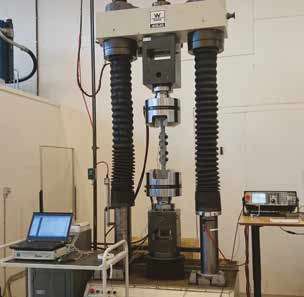
Figure 1. Amsler W Tester mounted with the test specimen
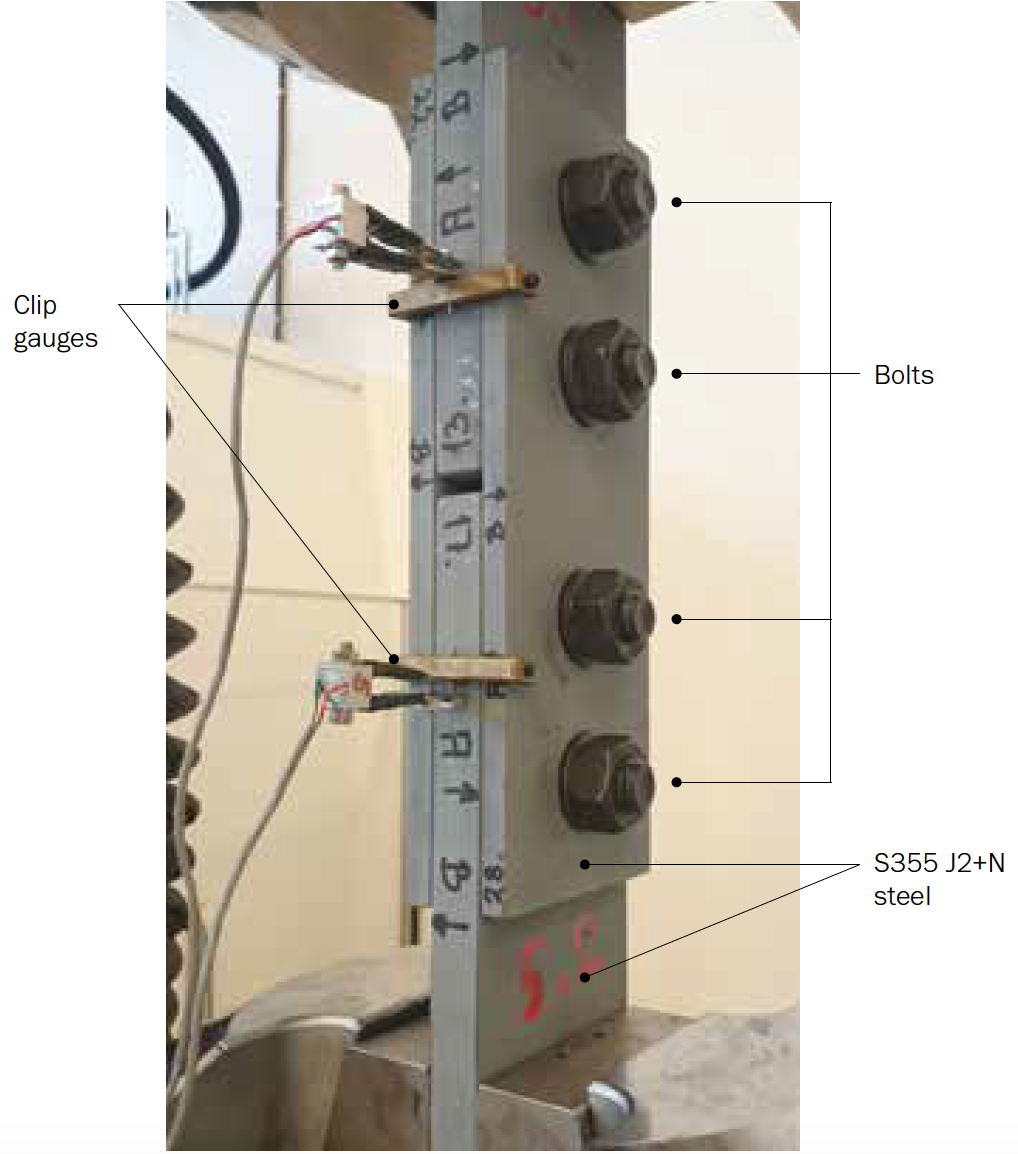
Figure 2. Details of the test specimen
Bolt preload tightening
Before assembling the four test plates of a test specimen, the preload force is calibrated against the torque to be applied – the ‘torque’ being the ‘turning force’ used to preload bolts.
The calibration of torques versus preload is carried out using a bolt strain gauge (see Figure 3).
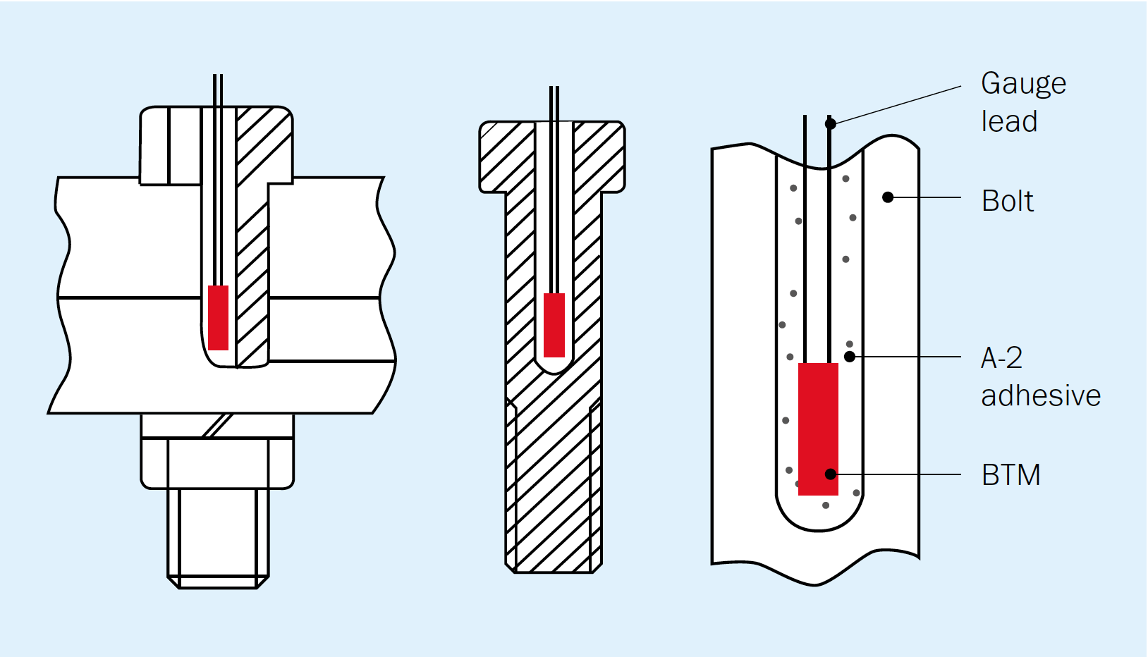
Figure 3. Example of bolt strain gauge glued inside the bolt before stressingvii
Slip test procedure
Figure 4 shows the outcome of the test on one specimen.
Two results are obtained from each specimen, one from each clip gauge. This gives 10 individual slip measurements from the 5 specimens. The individual slip load (FSi) is defined as the load at which a slip of 0.15 mm occurs.
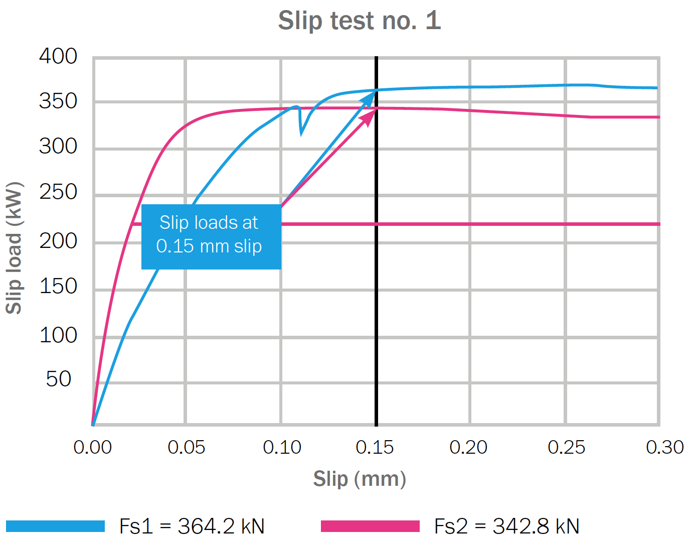
Figure. 4. Record from Test 1. The slip load at 0.15 mm slip is shown for each clip gauge
All slip factor test results are included in the test report and below.
Table 3

Table 3. Slip factor test results (Test report – Table 1)
The characteristic value is taken as the mean value minus 2.05 times the standard deviation according to Clause G.4.vi
In this test, the characteristic value is:
μ = 0.512-2.05∙0.022 = 0.46
However, because an extended creep test was required, the nominal slip factor is 0.40.
Extended creep test
The creep test is intended to ensure that the coated connection will not undergo significant creep deformation under sustained service loading. The purpose of the creep test is to assess that the creep of a connection will not exceed 0.3 mm over a period of 50 years when exposed to a load similar to that used for the delayed slip test, in this case 275 kN.
The test uses the same type of specimen as in the previous test. At least three test specimens, corresponding to six connections, are tested.
The test is carried out at three different times (16.5 hours, 67 hours and 70 hours).
The test results are extrapolated to demonstrate that the applied load will not cause displacement of the connection greater than 0.3 mm during the design life of the structure. EN 1090-2, G.5, suggests a 50-year design lifeix; the test extrapolates to a design life of 120 years, still using the displacement criterion of 0.3 mm. The test results are shown in Table 4.
An example of the ‘displacement log time’ curve is shown in figure 6, using the results from test specimen 6.
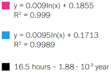
Table 4

Table 4. Extended creep test results, including extrapolated values for a design life of 120 years
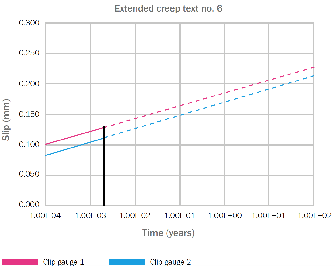
Figure 6. The ‘displacement log time’ curve for specimen no. 6, tested for 16.5 hours. The regression line is based on measurements taken every 60 seconds, approximately 1,000 measurements in all in this test
The six extrapolated slip values are all below the pass/fail criterion of 0.3 mm, even when extrapolated to 120 years.
Conclusion
This particular test report concludes:
- the mean slip factor value (μm) is 0.51
- the characteristic value of the slip factor (μ) is 0.46
- the slip factor is tested with a small coefficient variation of 4.2. This indicates a uniform friction surface characteristic
- one slip surface failed the delayed slip limit of 0.002 mm, while the other surface showed a slip value ten times lower than the required limit of 0.002 mm, namely 0.0002 mm
- all of the extended creep slips are significantly lower than the creep limit of 0.30 over the 120-year design life
The characteristic slip factor of 0.46 is 15 percent higher than the required slip factor of 0.40 for friction Class B.
The nominal slip factor of the system is 0.40, corresponding to the load used for the extended creep test. This means that the tested system can be classified as a surface friction Class B system according to Table 18 of EN 1090-2:2008 (see Table 1 above).
The test was carried out using property Class 10.9 bolts. This means that the slip factor according to EN 1090-2 may also be used for property Class 8.8 boltsx.
Notes on specification of coating systems for slip-resistant bolted connections
When specifying coating systems for slip-resistant bolted joints, it is important to adhere to the requirements of the test standard.
Accordingly, the fulfilment of the Essential Variables in RSCS Specification, A1.2 and EN-1090-2, Clause G.2vi must be met:
- the coating composition corresponds to the tested product/shade
- the surface preparation must be the same as used for the test
- a nominal dry film thickness should be specified for the test. It must meet the requirement of Clause G.3, which states that the dry film thickness tested must be at least 25 percent thicker than the nominal thickness specified for use in structures. According to RCSC Appendix A2.2, the specimens should be coated to an average thickness that is 2 mils greater than the maximum thickness to be used in the structure on both of the plate surfaces (the faying and outer surfaces)
- the curing procedure must follow the application instructions for the given coating system
- the minimum time interval between application of the coating and application of the load to the bolted connection should be the minimum curing time as outlined by the application instructions. (Applications instructions describes appropriate methods for accelerating curing and controlling curing conditions)
Other coating types than zinc silicate for slip-resistant connections
Inorganic coatings, such as zinc silicates, are often considered more difficult to apply than organic coatings, such as zinc epoxies.
A number of papers discuss the properties of zinc epoxy coatings in comparison with zinc silicates.
Kulakxi writes: “Use of inorganic zinc-rich paints for coating provides better slip resistance than when organic zinc-rich paints are used. When zinc silicate paint has been used with a clear lacquer (water-glass) as a binding agent and zinc dust powder as the pigment, high slip resistance has resulted. The increased hardness of the zinc silicate coating provides a more slip-resistant surface than surfaces treated with organic zinc-rich paints. For optimum results, these paints are generally applied to blast-cleaned surfaces by either spraying or brushing”.
Kulak concludes that when slip-resistant joints are subjected to sustained loading conditions, only surface treatments that provide adequate slip resistance under long-term loading should be used. Metallising with either zinc or aluminium, or a zinc silicate coating or a vinyl coating should be used. Hot-dip galvanising and organic zinc-rich coating systems are not satisfactory for slip-resistant joints. (Kulak’s inclusion of vinyl coatings seems incorrect, unless it covers the very thin zinc chromate polyvinyl butyrate used for temporary protection).
A. Cruz et alxii is a more recent source than Kulak. Their experimental work includes spray metallised zinc, hot-dip galvanising, zinc ethyl silicate and zinc epoxy.
Their conclusions are:
- slip factors with values of 0.50 are only obtained with blasted surfaces, without any additional surface treatment
- in blasted surfaces, spray metallised with zinc or hot-dip galvanised, the slip factor easily reaches values above 0.40
- blasted surfaces with a painted coating of zinc ethyl-silicate obtained a characteristic value of 0.40, but with only a small margin
- for blasted surfaces with a painted coating of zinc epoxy, the lowest slip factor values (not higher than 0.30) were obtained. The higher value was obtained for a zinc epoxy coating with a dry film thickness of 70 µm, while the lower slip factor of 0.20 was obtained at the higher dry film thickness of 135 µm
In 1984, Technical Committee 10 of the European Convention for Constructional Steelwork issued the report Slip factors of connection with H. S. F. G. bolts, (ECCS Publication No. 37xiii). The report’s conclusion on zinc epoxy coatings is that a slip factor for sustained loading is around 0.20-0.22 for dry film thicknesses between 10-25 µm and increases with dry film thicknesses up to 40 µm. (Higher dry film thicknesses were not investigated).
Looking at the above references, it is clear that zinc silicate coatings applied in dry film thicknesses of approximately 50 µm have a higher slip factor than zinc epoxy coatings.
One additional factor that is not considered when testing epoxy-based coatings is the change connected to temperature-dependent coating properties. One important temperature dependent is the glass transition temperature (TG) of the coating. At temperatures above TG, the organic binder changes from brittle to thermoplastic. This must mean the slip factor lowers compared to the slip factor at ambient temperatures. Many epoxy coatings have a TG around 50-60°C. Such temperatures are easily reached on sun-exposed structures. If zinc epoxy coatings are seriously considered for protecting slip joints, testing must also be carried out at higher temperatures.

-
References
i EN 1090-2:2008i Execution of steel structures and aluminium structures – Part 2: Technical requirements for steel structures.
ii Specification for Structural Joints using High-Strength Bolts. Research Council on Structural Connection (RCSC), Chicago 2014 (Includes 2015 Errata).
iii Kulak, G L, Fisher, J W, Struik, J H A: Guide to Design Criteria for Bolted and Riveted Joints. 2nd Ed. AISC, Chicago. 2001. Page 20
iv Maiorana, E and Pellegrino, C: Comparison between Eurocodes and North American and Main International Codes for Design of Bolted Connection in Steel Bridges. J. Bridge Eng., 2013, 18(12): 1298-1308
v EN 1090-2:2008, clause 8.4: Preparation of contact surfaces in slip resistant connections
vi EN 1090-2:2008, Annex G: Test to determine slip factor
vii http://www.tml.jp/e/product/strain_gauge/catalog_pdf/BTMseries.pdf
viii FORCE Technology, private communication
ix EN 1090-2:2008, Annex G, clause G.5: Extended creep test procedure and evaluation
x EN 1090-2:2008, Annex G, clause G.6: Test results
xi Kulak, G L, Fisher, J W, Struik, J H A: Guide to Design Criteria for Bolted and Riveted Joints. 2nd Ed. AISC, Chicago. 2001, Chapter 12, pages 197-216
xii Cruz, A, Simoes, R and Alves, R: Slip factor in slip resistant joints with high strength steel. Journal of Constructional Steel Research. Elsevier 2011
xiii ECCS, Slip factors of connection with H. S. F. G. bolts, ECCS Publication No. 37, 1984